LR Circuit with DC Source
LR Circuit with DC Source: Overview
This topic covers concepts, such as, DC Circuit, L-R DC Circuit, Derivation of Growth of Current in L-R DC Circuit & Derivation of Decay of Current in L-R DC Circuit etc.
Important Questions on LR Circuit with DC Source
A coil having inductance and resistance is connected to a battery of emf at . If and are the time for and completion of the current growth in the circuit, then will be-
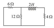
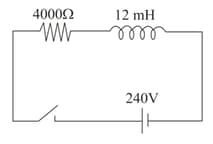
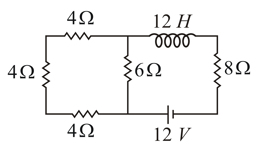
The time constant of the given circuit, containing an inductor and few resistors, is
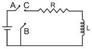
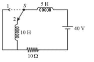
In the circuit shown here, the point '' is kept connected to point '' till the current flowing through the circuit becomes constant. Afterwards, suddenly, point '' is disconnected from point '' and connected to point '' at time . Ratio of the voltage across resistance and the inductor at will be equal to:
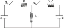
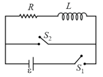
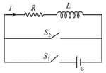
In the given circuit and are switches. is closed for a long time and remains open. Now is also closed. Here and . Let is the magnitude of rate of change of current (in ), just after is closed. The value for the inductor is . Then find .
When a circuit with is connected in series to an source of voltage a maximum rms current of is observed at frequency If this circuit is now connected to a battery of emf and internal resistance of the current will be
In the inductive circuit given in the figure, the current rises after the switch is put on. At instant when the current is then potential difference across the inductor will be :-
, respectively, indicate inductance, capacitance and resistance. Select the combination which does not have dimensions of frequency.
Identify the correct statement out of the following options regarding the given circuit.
For a certain inductive coil, it is known that its time constant is . If a resistance is joined in series with the coil, the time constant becomes . Hence, find the inductance and resistance of the coil.
With respect to the given L-R circuit, is the initial current and is the steady state current through the battery. Then, calculate the ratio .
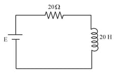
In a circuit, an inductance of and a resistance of are connected in series to a source of voltage . What is the time when the current in the circuit reaches half of its steady state value?
Calculate the time constant for the adjoining circuit that contains an inductor with a few resistors.
How much time does a solenoid of resistance require, to attain the magnetic energy equal to of its maximum magnetic energy, when connected to a battery?
In the circuit shown in the figure, the switch was kept in for a very long time and then at it is shifted to . The current in the circuit immediately after that is , then the value of is
At the switch is closed. Find the time after which the rate of dissipation of energy in the resistor is equal to the rate at which energy is being stored in the inductor.
In the circuit shown,
the switch is closed at time and the switch is kept open. At some later time , the switch is opened and is closed. The behavior of the current as a function of time ' ' is given by:
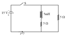
Find the current in the circuit long time after closing the switch.
In the given circuit, the switch is initially closed and is open. At any time , the switch is opened and is closed. The current vs time graph for the entire time during which it passes through the inductor is shown in figure. Then the best suitable graph is.
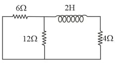
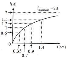
For given circuit, growth of current as function of time is shown in graph. Which of the following option represents value of time constant most closely for the circuit?
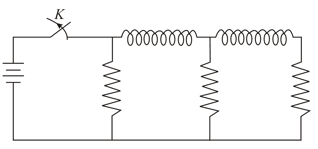
In the circuit shown below, all the inductors (assumed ideal) and resistors are identical. The current through the resistance on the right is after the key has been switched on for along time. The currents through the three resistors (in order, from left to right) immediately after the key is switched off are-